5G Cloud Nokia HEP3 Support
In Nokia SCP mode, the traffic is mirrored between the 5G control functions using HTTP2 protocol that is mirrored from a service called SCP (Service Control Proxy). The 5G-Cloud application receives the JSON encoded data from the VXLAN ingress TEPs. For details, refer to Nokia SCP.
Nokia HEP3 method is supported by Nokia for network functions across 3G,4G, 5G and the IMS core. HEP3 efficiently organizes and encodes data for various network protocols and enhances the functionality of Nokia's core network solutions by accommodating diverse packet requirements.
The 5G-Cloud application supports processing the Nokia HEP3 format from the non-SBI network functions – IMS network functions and 3G, 4G network functions. Non-SBI traffic is received as a TCP stream with HEP3 encoding by the 5G Cloud application. The 5G-Cloud handles non-SBI control traffic and leverages the robust capabilities of NokiaHEP3 (Homer Encapsulation Protocol Version 3) to encapsulate and transport data securely over TCP. Non-SBI control traffic is decoded from HEP3, emphasizing data handling without IP translation.
How Nokia HEP3 Solution works
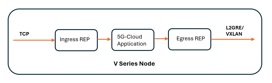
The following image shows the ingress and egress data flow through the V Series Node for Nokia HEP3 solution:
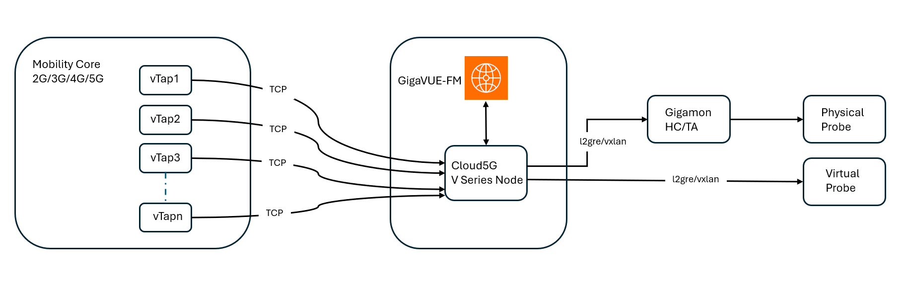
Traffic from the client vTAP systems is transported over TCP. The 5G-Cloud application processes and manages the incoming TCP traffic and terminates the TCP connection. The application then processes the TCP payload and synthesizes the data.
GigaVUE‑FM serves as the centralized management platform orchestrating the visibility fabric, which includes the 5G-Cloud V Series Node. The V Series Nodes inspect, aggregate, and process the incoming traffic. After processing, traffic is encapsulated using L2GRE or VXLAN tunneling protocols and forwarded to either physical or virtual probes as follows:
| Physical Probe: If IP connectivity is not available, the traffic is sent to a GigaVUE HC/GigaVUE TA Series device that serves as a traffic aggregator and distributor. The device decapsulates and distributes the traffic to the probe. |
| Virtual Probe: If IP connectivity is available, the processed traffic is forwarded directly to virtual probe for detailed traffic inspection and analytics. |
This end-to-end solution ensures comprehensive visibility into 5G network traffic, facilitating efficient monitoring and performance analysis across both physical and cloud-based infrastructures.
Configuration of 5G-Cloud Nokia HEP3
In GigaVUE-FM, perform the following to add the 5G-Cloud application in the Monitoring Session of a Monitoring Domain:
|
S.No |
Steps |
Refer to |
|
V series Node |
||
|
1 |
Create an ingress REP to receive the data over TCP |
Create Raw Endpoint (VMware vCenter) |
|
2 |
Add the 5G-Cloud application in the Monitoring Session |
|
|
3 |
Create a link between ingress REP and the 5G-Cloud application |
|
|
4 |
Create egress REP |
Create Raw Endpoint (VMware vCenter) |
|
5 |
Create a link between the 5G-Cloud application and egress REP |
|
Configure Nokia HEP3 in 5G-Cloud Application
Pre-requisite:
-
You must upload CSV files containing a valid FQDN and a valid IPv4/IPv6 address. For details, refer to Add CSV file for IP Mapping.
You can add a 5G-Cloud application to:
| New Monitoring Session: Add the 5G-Cloud application after creating a new Monitoring Session and when the GigaVUE-FM canvas appears. Refer to Create a Monitoring Session section in the respective GigaVUE Cloud Suite Deployment Guide. |
| Existing session: Select any existing Monitoring Session and go to TRAFFIC PROCESSING tab. The GigaVUE-FM canvas appears. |
To add a 5G-Cloud application,
| 1. | In the canvas, drag and drop the 5G-Cloud application and select Details. The 5G-Cloud quick view appears. |
| 2. | On the application quick view, enter or select the required information as described in the Reference - Configuration Table. |
Note: We recommend to maintain a 60-90 second delay when undeploying and deploying a Monitoring Session in GigaVUE-FM.
Reference - Configuration Table
|
Field |
Description |
||||||||||||||||||
|
Application |
The name 5g-Cloud appears by default. |
||||||||||||||||||
|
Alias |
Enter the alias name as cloud5g. |
||||||||||||||||||
|
Vendor Integrations |
From the drop-down list, select Nokia HEP3. |
||||||||||||||||||
|
SBI Operational Mode |
From the drop-down list, select the required operational mode from the following options:
Note: For software version 6.11, either mode functions identically. |
||||||||||||||||||
|
RX Tunnel |
|||||||||||||||||||
|
Type |
Specify the tunnel type. The default is TCP. |
||||||||||||||||||
|
Listening IP |
Specify the tunnel's local listen IP address to receive the packet. |
||||||||||||||||||
|
Listening Port |
Specify the tunnel's local listening port to bind to receive the packet. The application will listen to the traffic coming to the specified port. Enter a value between 1 and 65535. |
||||||||||||||||||
|
Source Port |
Specify the tunnel destination port from where the packets will be sent. Enter a value between 1 and 65535. |
||||||||||||||||||
|
TX Tunnel |
|||||||||||||||||||
|
Type |
Specify the tunnel type. The available tunnel types are:
|
||||||||||||||||||
|
Tool IP |
Specify the remote IP address to send the packet. |
||||||||||||||||||
|
Destination Port |
Specify the tunnel destination port to which the packet will be sent. Enter a value between 1 and 65535. |
||||||||||||||||||
|
Source IP |
Specify the source IP address to use when sending the packet. |
||||||||||||||||||
|
Source Port |
Specify the tunnel source port to bind when sending the packet. Enter a value between 1 and 65535. |
||||||||||||||||||
|
VNI Id (Applicable only when the selected tunnel type is VXLAN) |
Specify the VNI to use for the VXLAN traffic. Enter a value between 0 and 16777215. |
||||||||||||||||||
|
L2GRE Key (Applicable only when the selected tunnel type is L2GRE) |
Specify the key for the L2GRE tunnel type. Enter a value between 0 and 4294967295. |
||||||||||||||||||
|
Advanced Setting |
|||||||||||||||||||
|
Tool MTU |
Specify the tool port MTU. Note: For V Series Node version 6.8.00 and above, the range should be between 1400 and 8800. The default value is 8800. For V Series Node version below 6.8.00, range should be between 1500 and 8800. The default value is 8800. |
||||||||||||||||||
|
Log Directory |
Specify the path to store the log files. |
||||||||||||||||||
|
Log Level |
Select the severity log level of the events from the following options:
|
||||||||||||||||||
|
HEP3 Config |
|||||||||||||||||||
|
Number of Ingress TCP Connections |
Specify the number of concurrent TCP connections VTAP can establish. Enter a value between 128 and 2048. The default value is 1024. |
||||||||||||||||||
|
Ingress TCP Timeout |
Specify the timeout value for an Ingress TCP connection in seconds. Enter a value between 30 and 3600 seconds. The default is 60 seconds. Note: If no packets are received within the configured time, the TCP connection will be terminated due to timeout. |
||||||||||||||||||
|
Number of Egress TCP Flows |
Specify the total number of TCP Flows allocated for tracking non-SBI traffic. Enter a value between:
The default value is 4096. |
||||||||||||||||||
|
Egress TCP Flow Timeout |
Specify the timeout value for an Egress TCP flow in seconds. Enter a value between 30 and 7200 seconds. The default is 900 seconds. Note: If no packets are received within the configured time, the TCP flow will be terminated due to timeout. |
||||||||||||||||||
|
Number of Receiver Threads |
Specify the number of receiver threads for processing incoming packets. Enter a value between 1 and 128. The default value is 8. |
||||||||||||||||||
|
SCP Config |
|||||||||||||||||||
|
FQDN Mapping |
Select the alias name created for the uploaded FQDN table CSV file. |
||||||||||||||||||
|
NF Instance Mapping (Optional) |
Select the alias name created for the uploaded NFID table CSV file. |
||||||||||||||||||
|
User Agent Mapping (Optional) |
Select the alias name created for the uploaded User Agent table CSV file. |
||||||||||||||||||
|
TCP Server Ports |
Specify the TCP server port or port range to allow TCP communication between endpoints. Valid port range is between 1 and 65535. Note: TCP communication is allowed only on the configured ports. |
||||||||||||||||||
|
SCP Advanced Config |
|||||||||||||||||||
|
Packet Capture Level |
Select the packet capture level from the drop-down list:
|
||||||||||||||||||
|
Timestamp |
Select the required timestamp used to save the Egress PCAPs., The available timestamps are:
Note: Timestamp option will be disabled if the Packet capture level is set to None. |
||||||||||||||||||
|
5G-Cloud Log Level |
Select the required 5G-Cloud CSV log level from the drop down list. The default value is None.
|
||||||||||||||||||
Download Logs - 5G-Cloud application
You can view the log files of a V Series Node or download them as .CSV or .txt files.
To download the log files to a local environment,
| 1. | Go to Traffic > VIRTUAL > select your cloud platform. |
| 2. | Select the required Monitoring Session and go to TRAFFIC PROCESSING tab. |
| 3. | On the cloud5g application, click the  menu button and select Details. menu button and select Details. |
| 4. | Go to LOGGING in the quick view. The Logging page displays the logs currently available. |
| 5. | Select the required Days, Timestamps, File Name, and Type (TextLog and FlowStats) details. |
| 6. | Select the log files to download, and then click Download > Files. The system downloads the selected files to your local environment. |
Add CSV file for IP Mapping
To add the CSV file for IP mapping,
| 1. | Go to Inventory > VIRTUAL > select your cloud platform, and then click Settings > 5G-Apps. The 5G-Apps Configuration page appears. |
| 2. | Click New. Enter the name for the CSV file in the Alias field |
| 3. | From the Type drop-down list, select 5G-Cloud FQDN. |
| 4. | Click Choose File in the FileName field to upload the CSV file into GigaVUE-FM. |
| 5. | Add the CSV file containing a valid FQDN ID and a valid IPv4/IPv6 address for IP mapping. |
FQDN Mapping: gigamon@vseries:/var/log/cloud5g_tabledir$ cat FQDN.txt
| Header details: FQDNid,IngressIP1,IngressIP2,IngressPort,EgressIP,NFType,NFLocation,IMSIP,IMSIntfName,IMSMask,IMSType |
| Example: s25scp01.scp.5gc.mnc003.mcc525.3gppnetwork.org,170.00.13.187,,8080,,SCP,plolp,2000:4000:124:a0d9:ac1:4::,92,303 314 315,sbc |
The fields fqdnID and ingressIPAddress1 are mandatory. All other fields are optional.
The fields imsipaddress, imsinterfacename, imsmask and imstype are applicable only when the Integrated solution Vendor is "Nokia HEP3".
| 6. | Click Validate to validate the CSV file. |
| 7. | Click Save to add the CSV file. |
FHA Dashboards for 5G-Cloud Applications
After configuring the 5G-Cloud application, you can monitor the statistics for Ericsson SCP by the reports displayed in the Dashboard. To access the details, refer to FHA Dashboards for 5G-Cloud Applications.


